


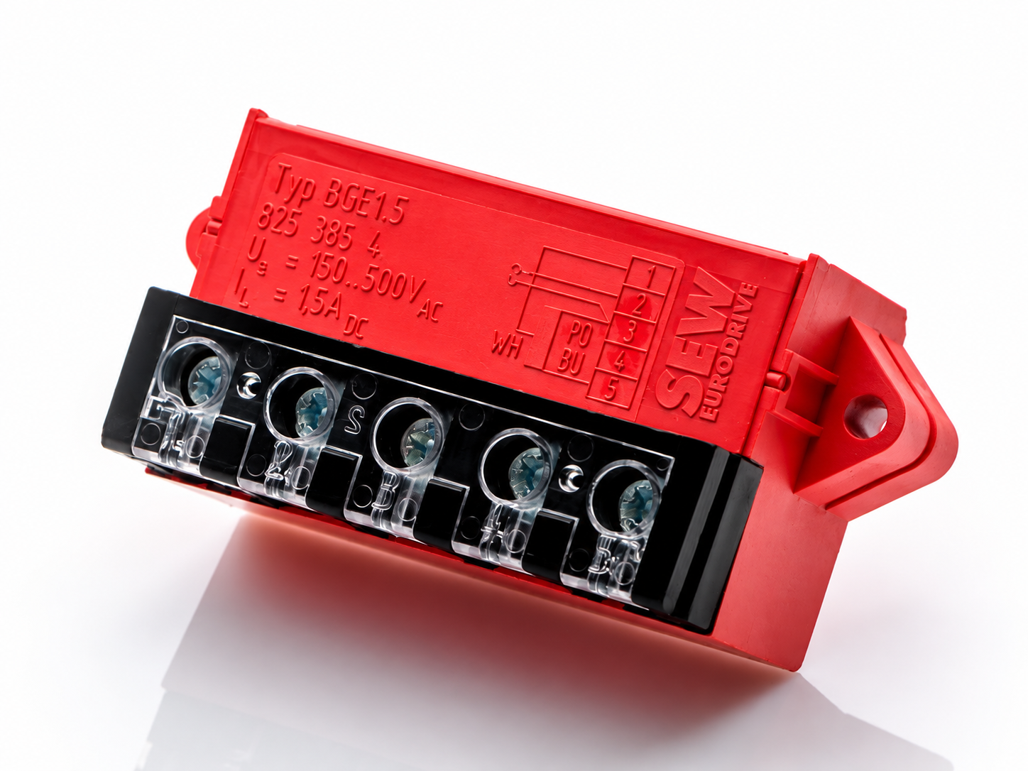
Always Check the Rectifier Markings When Connecting It
Brake rectifiers can often be used in different configurations, but this does not mean that the connection method is always the same. Before making the connections, check the markings on the rectifier and the correct wiring diagram for the given system.
The brake control method depends on the application. In systems requiring rapid stopping, solutions are used that enable faster brake deactivation. SEW-EURODRIVE indicates that simultaneous disconnection of the AC and DC circuits can significantly shorten the brake response time compared with disconnection on the AC side only.
This is particularly important in applications where high stopping accuracy is required, e.g. in equipment performing vertical movement.
Horizontal vs Vertical System – Rectifier Connection Method
Depending on the application, the rectifier connection method may vary.
In a horizontal system, a simpler control method is often used, in which two power supply wires are connected to the rectifier.
In vertical systems, e.g. in elevator drives or other lifting equipment, a system using additional wires and appropriate brake circuit control may be used. Such a solution can enable faster brake activation after the power supply is disconnected.
However, the number of wires should not be treated as a universal rule. The connection method should be determined by the rectifier type, manufacturer's diagram, brake type and requirements of the specific machine.
The connection diagram can often be found directly on the rectifier. See the image below.
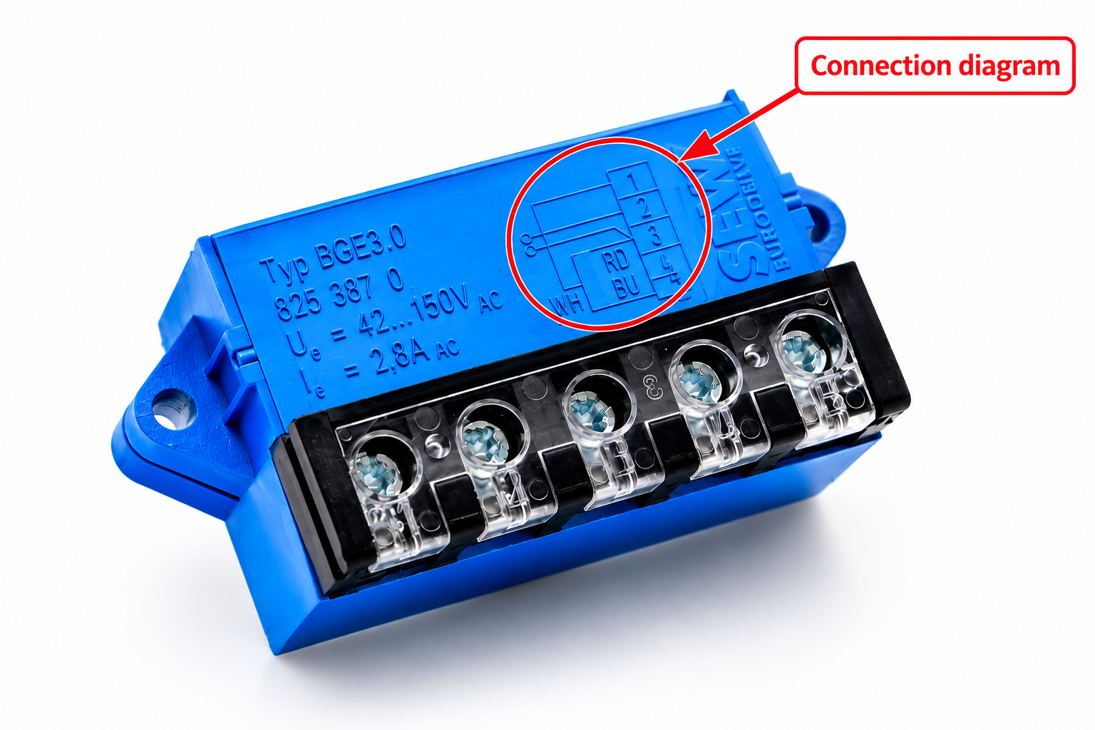
The symbols marked on the rectifier indicate the wire colours:
RD - (red) red colour
BU - (blue) blue colour
WH - (white) white colour
The Rectifier Should Be Selected According to the Operating Conditions
Rectifiers should be selected according to the requirements and operating conditions of the equipment. They can be installed directly in the motor terminal box or in the control cabinet.


SEW-EURODRIVE offers various brake control systems, including solutions with acceleration, rapid switch-off, heating or additional 24 V DC control inputs. The manufacturer also uses different housing colours as a colour code to make it easier to distinguish between individual versions. SEW-EURODRIVE rectifier colours
The housing colour can help identify the rectifier, but it should not be the only criterion for its selection. For example, SEW-EURODRIVE uses black, red, blue, brown, green, white and light blue housings, depending on the type and parameters of the brake control system.
Therefore, before replacing a rectifier, check its full designation, function and voltage range, rather than relying solely on the housing colour.
WH or WS – What Do These Symbols Mean?
When connecting a rectifier, different wire colour designations may be encountered.
If the rectifier or diagram uses the designation WS instead of WH, this may result from the use of the German colour designation instead of the English one:
WH = white
WS = weiss
Both designations refer to the colour white. The use of WS instead of WH does not in itself mean a change in the function or size of the rectifier.
Check the Brake Voltage Before Connecting the Rectifier
Before applying voltage, check what voltage the brake is designed for and what voltage range the rectifier supports.
The rectifier may have a wide input voltage range, but this does not mean that the brake coil can operate at any voltage within this range. You must check what voltage your brake or motor requires and connect that voltage. This information can be found on the brake or motor nameplate.
If the brake requires a different voltage than that supplied by an incorrectly selected or connected system, the brake may not operate correctly.
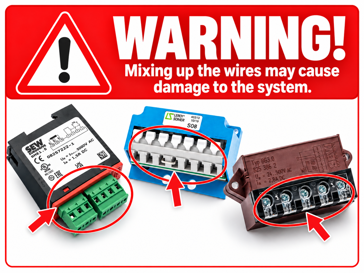
Mixing Up the Wires Can Damage the System.
When connecting the rectifier, it is particularly important to follow the manufacturer's diagram. The wires should not be connected based solely on their colour, the appearance of the rectifier or the previous connection method of a similar device.
Check:
-
rectifier designation and type,
-
brake coil voltage,
-
rectifier supply voltage,
-
terminal and wire designations,
-
manufacturer's wiring diagram,
-
required brake switch-off method.
Mixing up the wires or applying the wrong voltage may cause incorrect operation or damage to the brake or other system components.
Summary
When selecting a brake rectifier, you should not rely solely on its appearance. You need to take into account the rectifier designation, brake voltage, rectifier voltage range, control method and application requirements.
Particular attention should be paid to installations requiring rapid stopping. The appropriate method of disconnecting the brake circuit can significantly shorten its response time.
If you have any problems selecting or connecting a rectifier, we will be happy to help:
Tel. 0048 63 261 42 02
E-mail: biuro@polberis.pl
You can find rectifiers here >>Click here<<